What matters is what arrives
Various measurement techniques are used in fiber optic deployments—one of them is the
Optical Loss Test Set (OLTS). It calculates the optical signal loss between two points by
comparing transmitted and received power levels. But what exactly is being measured, and
why is this value so critical for evaluating fiber link quality? Here’s a brief overview.
“If the fiber is installed properly and light is transmitted, it should just work.” – Statements like this are still frequently heard in the field. In practice, however, things are not always that simple. This is why a variety of measurement techniques have been developed in fiber optic technology. This article focuses on one of the most straightforward yet highly effective methods: the Optical Loss Test Set.
Let’s start with a simple analogy: when replacing a lightbulb at home, even a child knows what to do – flip the switch and see if the light turns on. So why should this basic and proven principle be any different when rolling out fiber optic infrastructure? If no fault is suspected and the fiber is assumed to be properly installed, a light signal is injected at one end of the fiber, and the amount of light received at the other end – after 2, 4, or even 8 kilometers – is measured. This is precisely what an Optical Loss Test Set does.
The specific transmission technology – whether point-to-point, PON, or similar – plays little role at this stage. As long as the signal arrives reliably and a sufficient power margin is maintained based on the sensitivity of the receivers, the installation can be considered to meet the basic requirements. This provides a valuable form of verification, particularly when handing over completed fiber segments to the client.

Connection of OLS and OPM for Out-of-service or In-service (overlay) measurement.
Optical loss testing: What’s actually measured?
What is commonly referred to as an attenuation measurement is, in fact, a measurement of the optical power level at the end of the fiber. Technically, this is an optical power measurement – not a direct measurement of attenuation.
The key difference from basic power level readings on live systems lies in the fact that, during an optical loss test, there is no active light source present on the fiber. The measurement setup must therefore include one.
An Optical Loss Test Set always consists of two components: an Optical Light Source (OLS) and an Optical Power Meter (OPM). The OLS injects a defined optical signal into the fiber at a specified wavelength, with minimal insertion loss, allowing accurate measurement at the far end.
The attenuation of a fiber link is determined by calculating the difference between a known and calibrated transmit power and the precisely measured receive power at the far end of the fiber. In other words, attenuation is not directly measured – it is calculated.
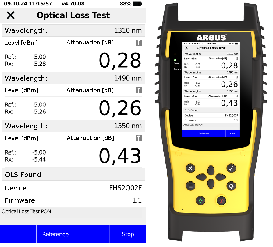
Result display of an automated Optical Loss Test (out-of-service) across three wavelengths.
Optical Light Source
A typical insertion power level suitable for most fiber links and technologies is around -5 dBm – commonly referred to as the transmit power. Using higher levels, such as those comparable to an OLT (Optical Line Terminal), would increase the risk of non-linear effects and could lead to inaccurate readings due to power meter saturation.
Additionally, lower power levels are safer for the user: a level of -5 dBm corresponds to approximately 0.3 mW, which is considered eye-safe. While OLTs are designed to deliver usable signals over long distances, an Optical Light Source is optimized for precise and controlled measurement conditions.
It is essential that the light source transmits at a constant power level and a stable wavelength. Variations of up to ±0.5 dB in output power and an additional ±0.1 dB over time, as well as wavelength deviations of up to ±10 nm, are generally acceptable.
Ideally, both the Optical Light Source and the Optical Power Meter should be factory-calibrated and delivered with a calibration certificate. Recalibration is strongly recommended every two years to ensure continued measurement accuracy.
In most cases, two wavelengths are sufficient to simulate the vast majority of singlemode fiber technologies. The most fundamental one is 1550 nm, which falls within the third optical transmission window and offers the lowest attenuation per kilometer.
This wavelength is also frequently used to carry the video overlay signal in GPON or XGS-PON networks, enabling long-range, unidirectional downstream transmission of broadcast TV content.
The second recommended wavelength is 1310 nm, which lies within the second optical transmission window. It is commonly used for upstream transmission in GPON networks as well as in active point-to-point systems such as fiber-based Ethernet and AONs (Active Optical Networks).
An important advantage of 1310 nm is its low chromatic dispersion. This matters because real-world laser sources are not perfectly monochromatic – they emit light over a spectral range. As a result, different spectral components (shorter vs. longer wavelengths) travel at slightly different speeds, arriving at the receiver at different times. This causes signal broadening and distortion, which can become critical over long distances or at high data rates.
For added reliability, it is recommended to include a measurement at 1490 nm as well – this is the primary downstream wavelength used in standard GPON networks.
Additionally, the wavelength 1625 nm can be used for so-called in-service measurements. Even if the fiber link is already active and transmitting data between the OLT and ONT (Optical Network Terminal), an overlay test can still be performed.
In this case, the Optical Light Source is temporarily inserted on the OLT side to approximate the optical loss without taking the entire branch out of service. It is important to ensure that the ONTs in the network are capable of filtering out the 1625 nm signal to avoid interference.
When using a multi-wavelength OLS – such as one supporting 1310, 1490, and 1550 nm – to evaluate the optical loss of a fiber link for GPON deployment, it is extremely helpful if the OLS can communicate its current transmit power and wavelength directly to the OPM.
This allows the power meter on the receiving side to automatically detect and measure each wavelength in sequence and display all results clearly within seconds. Such protocol-based, automated transmission of wavelength and transmit power (Tx power) eliminates the need for manual adjustments.
This auto-mode is particularly valuable during the commissio-ning of hundreds of newly installed fibers, as it not only saves significant time but also reduces the risk of user error. It is a crucial feature that should not be overlooked when selecting measurement equipment.
An in-service measurement at a wavelength such as 1625 nm should always be provided via a dedicated connection – for example, through a separate SC/APC port. This helps prevent accidental transmission on live wavelengths such as 1310, 1490, or 1550 nm, which could interfere with active network users.
One often overlooked but essential feature is measurement
logging. Basic solutions may only display values via a 7-segment indicator or, in more modern devices, on an LCD screen. However, if these values cannot be saved or transferred – whether to the cloud, a PC, smartphone, or database – the result is a cumbersome and error-prone manual documentation process.
Mistakes in recording, assigning, or forgetting values are common in such cases. Today, export formats such as HTML or CSV, which can be quickly retrieved from the test device via smartphone, as well as transmission methods like QR code scanning, have become standard – and are virtually indispensable.
Documented acceptance measurements not only serve as proof of workmanship, but can also – if not already contractually required – be offered as an additional service to the client. In case of disputes, such measurement reports may serve as independent quality evidence and can be of critical importance.
As important as technical specifications and high measurement accuracy may be, one principle always takes precedence in the field: absolute cleanliness and physical integrity of all fiber connectors must be ensured at all times.
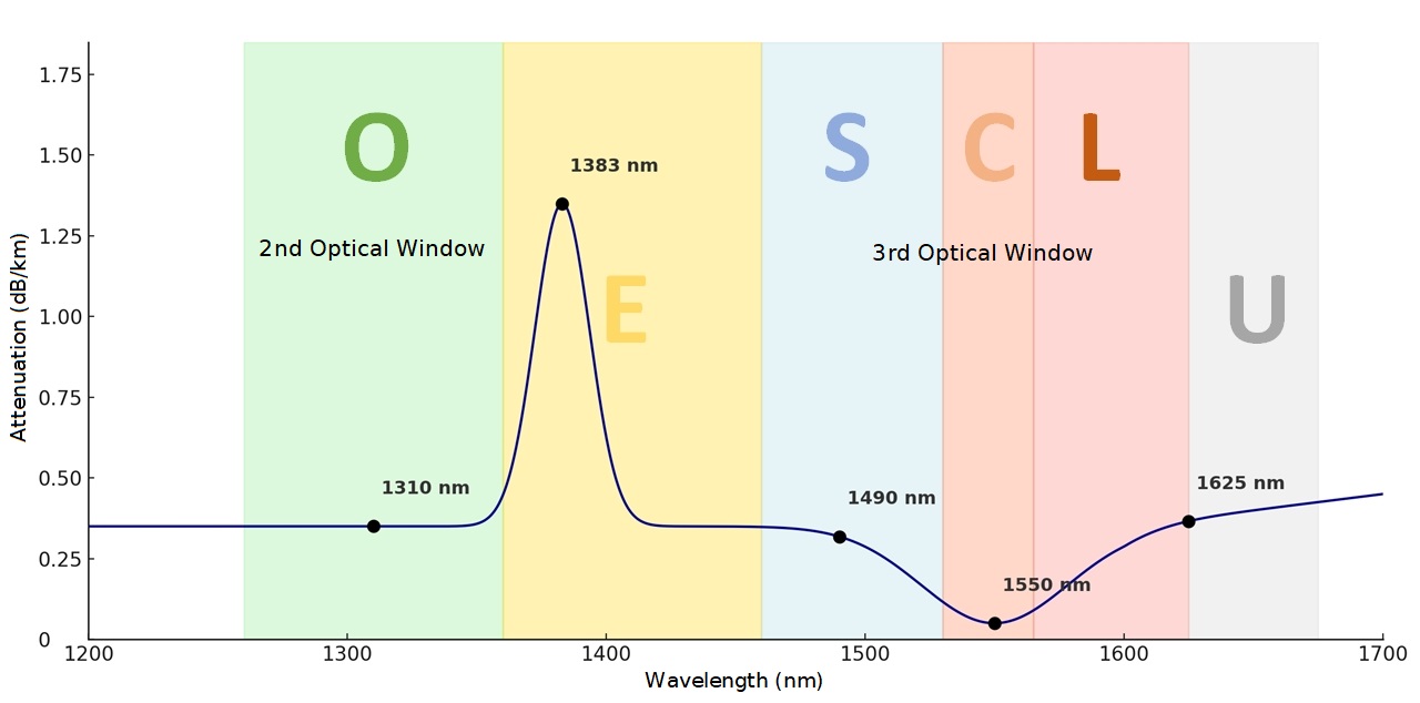
Realistic attenuation curve of a singlemode fiber (PON) showing bands and the second and third optical windows.
Challenges and solutions
The market offers a wide variety of solutions, and each application area comes with its own specific requirements when it comes to selecting the right equipment. Should you opt for a kit consisting of two separate devices in a transport case, or a single unit that integrates all necessary functions?
Even when you are fully aware of the technical parameters to consider, flexibility remains a key advantage. Application scenarios and user requirements often change – particularly with regard to acceptance testing and documentation for new installations. These changes may be driven by shifting customer expectations or evolving standards and regulations.
intec Gesellschaft für Informationstechnik mbH develops high-precision measurement solutions for a wide range of applications. For example, existing test devices – some originally intended for DSL applications and equipped with an SFP port – can be upgraded into a full OLTS simply by adding a compact SFP-based Optical Power Meter.
Even previously acquired OTDR devices or dedicated PON speed meters featuring real ONT simulation and IP speed tests up to 10 Gbit/s can be expanded this way – quickly, cost-effectively, and without needing to send in the device. This is a strong argument for intensive field deployment.
And if the SFP slot in the unit becomes worn out from repeated use, it can easily be replaced by swapping the module – another practical benefit of modular, SFP-based systems.
The solutions developed and manufactured entirely in Germany by intec, based in Lüdenscheid, cover the full spectrum of fiber optic measurement technology – from simple retrofit options via SFP modules, to compact and cost-effective power meters (3xOPM) for filtered, selective measurements at key live wavelengths such as 1490 nm (GPON) and 1577 nm (XGS-PON), all the way to broadband OPMs for full OLTS operation.
In addition, intec offers multifunctional devices that combine OTDR, 5xOPM with through-mode, fiber end-face inspection tools, and comprehensive connectivity testing for GPON, XGS-PON, Ethernet, WLAN, and OLTS functionality – all in a single system.
Conclusion and outlook
The advantages of using an Optical Loss Test Set are clear: it offers high measurement accuracy when determining the actual loss over a fiber link – particularly for acceptance tests after installation or maintenance. Further benefits include compliance with numerous national and international standards (such as ISO/IEC 14763-3 and TIA-568), a fast and simple test setup, and easy operation and data interpretation.
However, OLTS also has its limitations: it cannot provide precise fault localization or reflectance measurements. For these, an Optical Time Domain Reflectometer (OTDR) is still required. Additionally, OLTS testing depends on having access to both ends of the fiber.
An OTDR is ideal for fault localization, but not for precise loss measurements. An Optical Power Meter (OPM) only displays the power received from active equipment – such as the transmit level of an OLT. To accurately determine the link loss, an additional constant light source and a reference measurement are required.
An Optical Loss Test Set simply delivers greater accuracy – because ultimately, what matters most is how much signal actually arrives at the end of the fiber.
Download the professional article as PDF here.