When do I need a power meter for FTTH, and when do I need an OTDR?
During the installation, acceptance testing, or troubleshooting of an FTTH connection, power meters and OTDRs are used for different tasks. An Optical Power Meter (OPM) measures how much optical power arrives at a specific measurement point. An OTDR (Optical Time Domain Reflectometer), on the other hand, analyzes the fiber-optic link and can identify where a fault or unusual attenuation is located.
In simple terms, the difference can therefore be boiled down to two questions:
Power meter: How much optical power is reaching the destination?
OFL/OTDR: Where along the fiber-optic link is the problem located?
The two measurement methods complement each other: If the level measurement indicates an abnormal value, a reflectometric measurement using OFL or OTDR can then be used to pinpoint the cause.
When do I need a power meter for FTTH?
An optical power meter is used to measure the optical level at a specific point along a fiber-optic connection. This allows one to verify, for example, whether sufficient optical power is reaching the subscriber's connection.
A selective or filtered PON power meter is particularly useful for active GPON or XGS-PON accesses. GPON uses 1490 nm for the downstream and 1310 nm for the upstream, while XGS-PON uses 1577 nm and 1270 nm, respectively. If multiple signals are transmitted simultaneously over the same fiber, the individual wavelengths must be measured separately.
A simple overall level is not sufficient for an unambiguous assessment. A selective power meter can measure individual wavelengths separately and thus determine the respective optical levels.
When do I need an OTDR for FTTH?
For example, if the level measurement indicates excessive attenuation, it does not yet reveal where along the fiber-optic link the cause lies. This is where an OTDR comes into play.
An OTDR transmits a defined optical pulse into the fiber and analyzes the backscattered and reflected signal components. This allows events along the fiber-optic link to be detected and located.
Depending on the measurement, the following events and characteristics of the fiber-optic link, among others, can be identified and analyzed:
- Line Length and Fiber End
- Connectors
- Splices
- Bends
- Attenuation Events
- Reflections
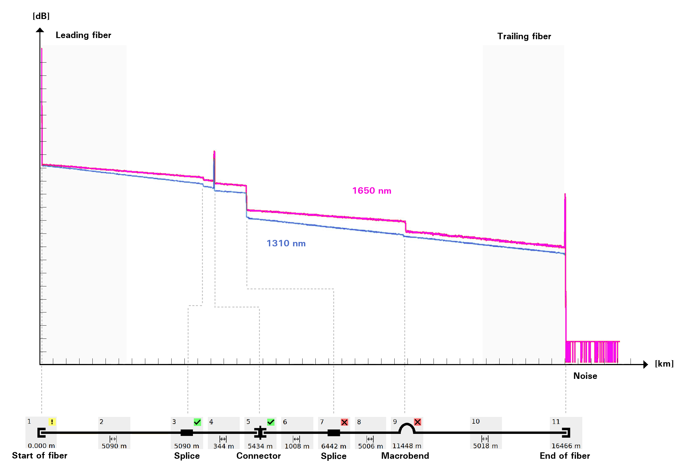
OTDR measurement curve of a fiber-optic link with splices, connectors, macro-bends, and fiber ends at 1310 nm and 1650 nm
How does troubleshooting work for an FTTH access?
This results in a simple troubleshooting process:
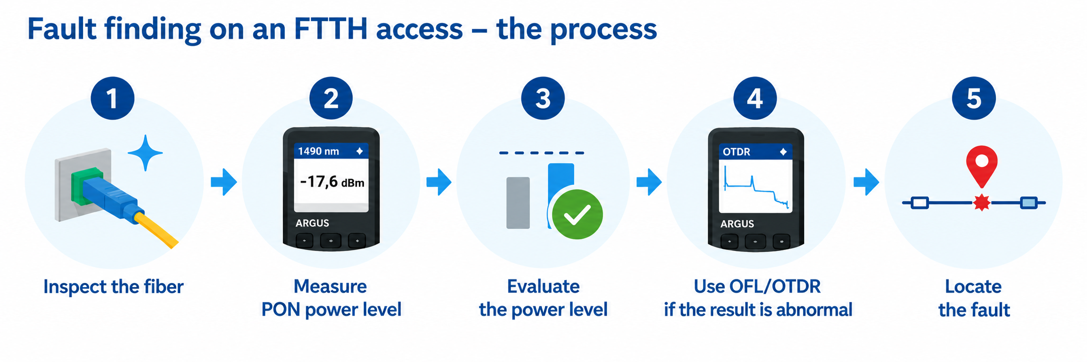
Inspect the fiber → Measure the PON level → Evaluate the level → If the result is abnormal, use an OFL/OTDR → Locate the fault
Power meters and OTDRs are not competing measurement methods. They answer different questions and can complement each other during troubleshooting.
What is the difference between OFL and OTDR?
The full range of measurement and analysis capabilities of an OTDR is not required for every service call. An Optical Fault Locator (OFL) can be used for quick fault location.
OFL and OTDR are both based on reflectometric measurements, but they serve different purposes. An OFL narrows the measurement down to the information relevant to the service and guides the technician—as automatically as possible—to any anomalies. Detected anomalies and their locations are displayed in an easy-to-understand format.
A full-featured OTDR also provides detailed information about the entire fiber run and enables a more in-depth analysis of attenuation, reflections, splices, and connectors.
OFL or OTDR—which method is best suited for which application?
| Question / Application | OFL / Simplified fault location | Full-featured OTDR |
|---|---|---|
| What do I want to know? | Where does a notable event take place? | What exactly happens along the entire fiber-optic route? |
| Typical User | Installation and Service Technician | Fiber Optics Technician / Measurement Technology Specialist |
| Operation | Guided, largely automated analysis | Automatic or detailed manual analysis |
| Presentation | Events and distances presented in an easy-to-understand format | Event table and complete OTDR curve |
| Locating Errors | Yes | Yes |
| Detailed Characterization of Splices and Connectors | Limited | Yes |
| Determine Event Attenuation | Limited | Yes |
| Analyze Line Attenuation | Limited | Yes |
| ENT / Reflection Analysis | Limited | Yes |
| Manual Detailed Analysis | Not the primary goal | Yes |
| Key Focus Area | Quick Troubleshooting on the Last Mile | Comprehensive inspection and detailed fiber diagnosis |
| Key Advantage | Quick, Clear Service Message | Maximum depth of measurement and analysis |
Which ARGUS testers are suitable for power meter, OFL, and OTDR measurements?
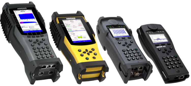
Depending on the application, various ARGUS testers are available for measurement and fault location. The ARGUS® F200 and ARGUS® F240 can combine PON measurement functions with the Optical Fault Locator (OFL) to simplify fault location. The ARGUS® F300 and ARGUS® 300 combine PON measurement functions with a full-featured OTDR.
This allows for immediate fault localization or detailed fiber analysis following an abnormal level reading, without having to switch to a separate measuring device for the next measurement.
ARGUS F200 | ARGUS F240 | ARGUS F300 | ARGUS 300 | ARGUS 260
| Specifications | ARGUS OTDR |
|---|---|
| Measurement Methods | Optical Time Domain Reflectometer (OTDR) |
| Wavelengths | 1310 + 1650 nm or 1310 + 1550 nm |
| Dynamic Range | up to 37 dB |
| Event Dead Zone | 0.9 m |
| Attenuation Dead Zone | 3.5 m |
| PON Dead Zone | ≤ 25 m, typically 20 m |
| Display Area | 250 m to 240 km |
| Measurement Modes | Smart Auto, Expert, Real Time up to 4 Hz |
| Detected Events | including connectors, splices, and bends, among other things |
| Insertion Loss (IL) | Yes |
| Optical Return Loss (ORL) | Yes |
| Macrobend Localization | Yes, by comparing two wavelengths |
| Leading fiber can be used | Yes |

on the road

We are at the Breitbandforum Mecklenburg-Vorpommern:
05 November 2026
in Rostock-Warnemünde
Booth S17

Visit us at the Fiberdays27:
17 - 18 February 2027
in Frankfurt am Main

Visit us at ANGA COM:
01 - 03 June 2027
in Cologne