How do I find out where a fault is located on an active PON?
An optically low signal level at a GPON or XGS-PON access initially indicates only that a problem exists—not where it is located. To perform targeted troubleshooting, the technician must therefore determine at which point along the fiber-optic link the abnormal attenuation or other event is occurring.
Is the problem right at the access, at a connector or splice—or several hundred meters away on the feed line?
Reflectometric measurement methods such as OFL (Optical Fault Locator) and OTDR (Optical Time Domain Reflectometer) are used to locate such faults.
How can a fault in a fiber-optic cable be located?
An OTDR transmits an optical pulse into the fiber optic cable and analyzes the backscattered and reflected signal components. Based on their intensity and transit time, events along the path can be detected, and their distance from the measuring device can be determined.
Depending on the measurement, the following events, for example, can be pinpointed:
- Connectors
- Splices
- Bends
- Notable attenuation events
- Fiber ends and fiber breaks
Thus, the reflectometric measurement not only indicates that the level is too low, but also provides a specific clue as to where along the fiber-optic link the cause should be sought.
Can I use an OTDR on an active PON?
When a PON is active, the measurement must be performed in such a way that ongoing GPON or XGS-PON data traffic is not disrupted.
For such in-service measurements, a maintenance wavelength separate from the user signals can be used. 1650 nm lies outside the transmission wavelengths used for GPON and XGS-PON and can therefore be used for fault location on an active PON.
This allows the fiber-optic link to be inspected while the PON remains in operation.
What is the difference between an OFL and an OTDR when troubleshooting?
For a service technician, a complete analysis of a traditional OTDR curve is not necessary in every fault situation. Often, two questions are crucial at the outset:
What stands out along the route?
How far is this event from the measurement point?
This is where the Optical Fault Locator (OFL) comes in. It simplifies reflectometric fault location and processes detected events so that the technician does not have to analyze a complex OTDR curve on their own.
A full-featured OTDR, on the other hand, offers greater measurement and analysis capabilities and is suitable when events on the fiber-optic link need to be examined and evaluated in greater detail.
Learn more: OFL or OTDR—which measurement method do I need for FTTH?
How does fault localization work on an active PON?
The typical process can be broken down into just a few steps:
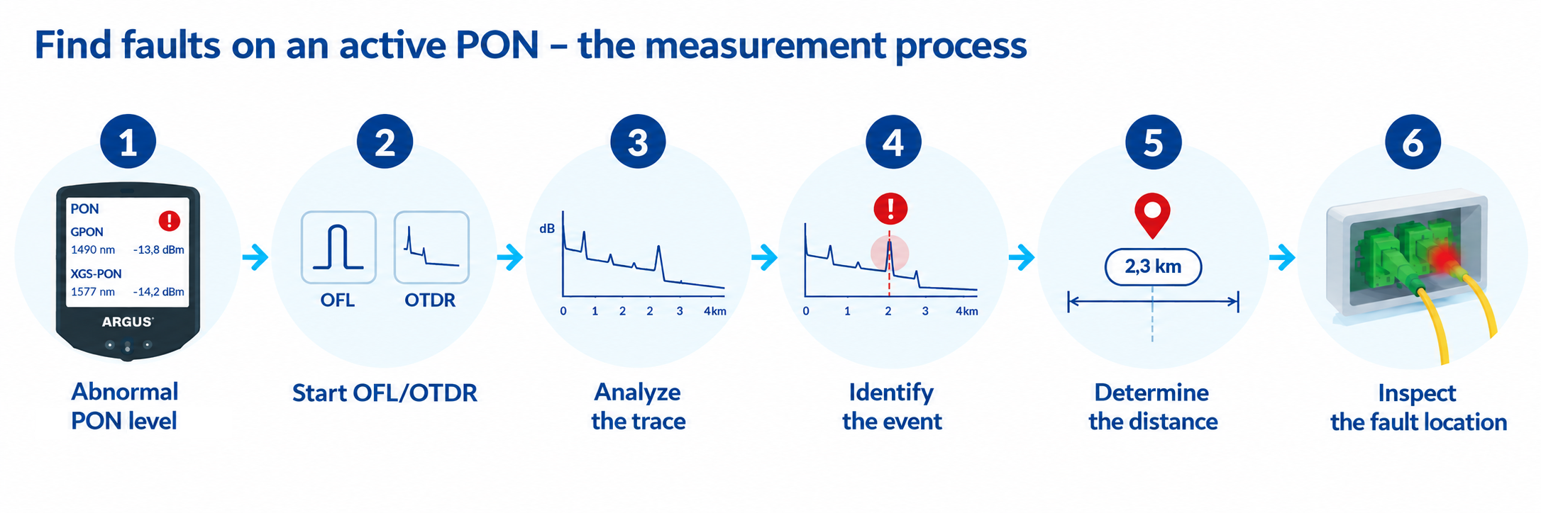
PON level abnormal → Start OFL/OTDR → Analyze the link → Identify the event → Determine the distance → Check the fault location specifically
Instead of checking multiple splitters, connectors, or other potential points of failure one after another, this provides the technician with a specific indication of the distance at which an anomaly is located along the fiber-optic link.
Which ARGUS testers are suitable for fault location?
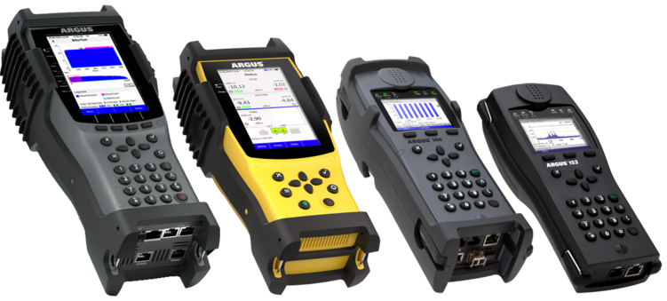
For typical service calls, the ARGUS® F200 and ARGUS® F240 can be used with the Optical Fault Locator (OFL) to simplify fault location.
The ARGUS® F300 features a full-featured OTDR for more detailed measurements. This allows events on the fiber-optic link to be located and analyzed in greater detail.
ARGUS F200 | ARGUS F240 | ARGUS F300
The key benefit for troubleshooting: The statement
“The optical level is too low.”
is transformed into much more specific information:
“The anomaly is located on the fiber-optic line at this distance.”

on the road

We are at the Breitbandforum Mecklenburg-Vorpommern:
05 November 2026
in Rostock-Warnemünde
Booth S17

Visit us at the Fiberdays27:
17 - 18 February 2027
in Frankfurt am Main

Visit us at ANGA COM:
01 - 03 June 2027
in Cologne